Low slope roofs or “flat” roofs, as they are sometimes called, typically have single-ply membrane or multi-layer “built-up” roof systems. Although one or more manufacturers offer warrantees for membranes installed with no slope (dead level), the 2009 IBC (International Building Code) requires a minimum slope of 1/4 inch per foot for most types of roof membranes. The IBC makes an exception for coal tar pitch systems, allowing a minimum slope of 1/8 inch per foot, due to the tendency of the material to move on slopes greater than that. Although the popularity of roofing systems changes over time and from region to region, the single ply membranes most commonly used at this time for low slope roofing include EPDM (think of it as rubber), PVC, and TPO. EPDM systems typically employ solvents for sealing seams, while PVC and TPO membranes have heat-welded seams. The comparable costs of these systems are not fixed but depend on the manufacturer, the installer, the region, and other market factors. (I have been involved in projects where we requested alternate bids for different systems, expecting one type to cost more than the other, then seeing bids that differed in terms of comparative costs (EPDM more than PVC from one bidder, and EPDM less than PVC from another).)
The surface slopes of low-slope roofs typically rely on a combination of sloping structure and tapered insulation. Low-slope roofs that are complex in plan commonly include a “warped” roof structure to provide the primary drainage slopes and include limited areas of tapered insulation to redirect drainage where it is not practical to slope a limited area of the structure in the necessary direction. The “warping” of the roof structure is typically achieved by adjusting the elevations at tops of columns up or down to generate the desired slope from column to column orthogonally or diagonally or both. Where the roof areas are large and the runs to roof drains are long, it may be necessary to consider the minimum slope for the longest run to the drain and then interpolate to establish the required roof deck elevations at column points in the tributary drainage area. If the roof structure itself includes cantilevered beam connections, where the connections from beam to beam are some distance away from the columns, then the elevations at the connection points should be the basis for the drainage design, and column point elevations should be established by interpolation from the connection point elevations.
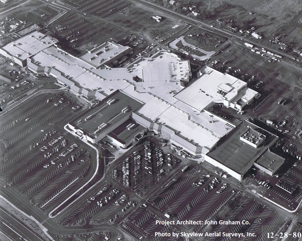
Sound complicated? It can be. The not-so-flat roof can be not-so-easy to design. Given the possible complexities of plan shape, perimeter conditions, top-of-wall and roof-edge design intent, space for ducts and equipment in available ceiling space under the roof, and economical use of roof drains and tapered insulation, it can take several passes at one or more areas of a roof to achieve a roof design that meets all criteria. The photo below shows a complex roof layout over a mall; the slopes for drainage above the mall and shops needed to consider the meandering path of the rectangular skylights above the mall (the intended high points of the roof), the varying distances to low points, roof heights that would screen mechanical equipment behind the perimeter mansard roof, cantilevered beam connections, and other factors. (Although the drainage layout for the roof in the photo was designed in the late 1970’s, water on a surface behaves in the same way today, so the principles of roof drainage design are essentially unchanged.)
One “trick” that can help the designer visualize the roof surface that is being warped is to consider the roof plan a topographic map with contour lines. Exaggerate the vertical change (e.g., convert inches to feet) just for the purpose of visualizing drainage patterns, and sketch contour lines on a working draft.
It also helps to know some algebra and trigonometry. Or, if you use a program that does the calculations for you, you just need to check the results to be sure they make sense.
Leave a Reply